
Vehicle-motion context; not a sensor test or product demonstration. Photo: Maksim Tarasov / Unsplash.
Automotive Safety MEMS: Qualifying the Diagnostic Chain
Integrated automotive motion sensors can simplify hardware while leaving substantial safety work at the system boundary. STMicroelectronics’ latest launch makes that distinction timely: commercial readiness, diagnostic features and a common interface help only when the controller can recognize invalid measurements and respond appropriately. The strategic opportunity lies in documented integration and verifiable failure behavior, alongside nominal sensor performance.
MEMSWork Intelligence Dashboard
| Field | Current assessment |
|---|---|
| Market status | ST reports the new combination sensors in production; vehicle-program adoption is not established by the announcement. [1] |
| Primary constraint | Demonstrating that faults are detected, communicated and handled within the application’s safety requirements. |
| Demand driver | Combining motion sensing with active and passive vehicle safety functions. [1] |
| Time horizon | Component evaluation now; customer qualification and deployment schedules remain undisclosed. |
| Technologies to watch | Sensor self-test, signal-chain diagnostics, protected communication and ECU integration. [2] [3] [8] |
| Strategic signal | Purchase an integration evidence package alongside the sensor. |
| Next trigger | Customer validation showing defined fault responses and measurable integration savings. |
The decision question: does integration reduce safety work?
On October 26, 2026, STMicroelectronics announced automotive combination sensors that integrate acceleration and angular-rate sensing for functions including stability control, rollover detection and crash protection. ST says the devices are in production and support SafeSPI. This is a commercial component launch, rather than a laboratory demonstration. It does not disclose customer deployment volumes or prove lower vehicle-system cost. [1]
The decision question is whether the integrated component reduces the effort required to deliver a dependable safety function. That requires examining the route from physical motion through signal processing and communication to the controller’s response. MEMSWork’s thesis is that a shared sensor platform creates durable value when its diagnostic evidence can be reused across applications without concealing application-specific assumptions.
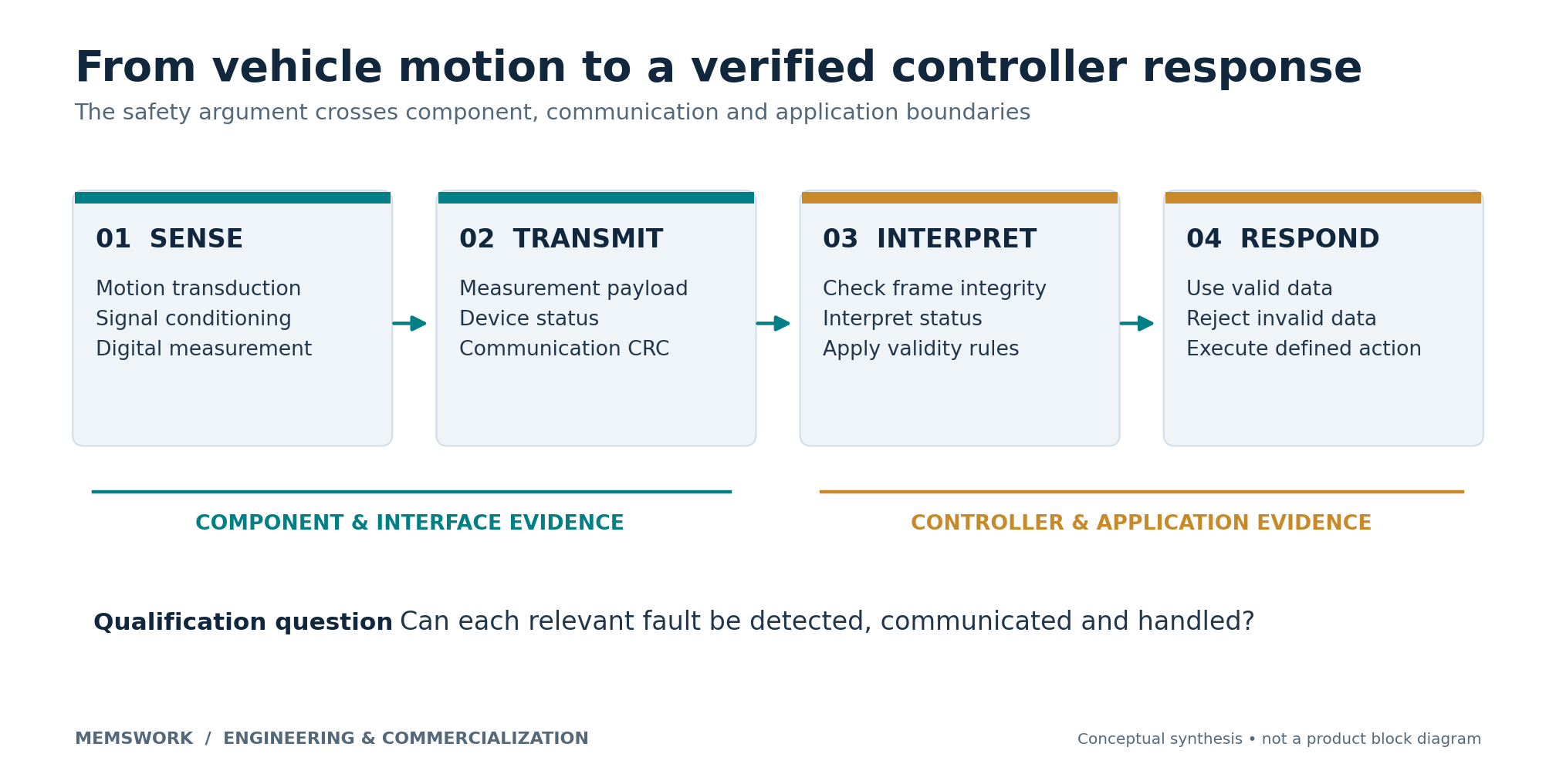
What changed: a configurable safety-sensor platform
The NCS1012BAEP combines yaw-rate sensing with acceleration along the x and y axes. Its listed angular-rate full-scale settings are ±125, ±250 and ±350 degrees per second; the operating range is −40°C to +105°C. The product page describes independent acceleration signal chains from analog-to-digital conversion to the communications interface. Those are useful architectural facts, but they do not quantify independence against every common-cause failure. [2]
The NCS1012EAEP instead combines roll-rate sensing with x/y acceleration and offers a higher acceleration range, with a listed upper nominal full scale of ±150 g. [3] Selecting axes and range should follow the safety function, mounting and motion envelope. A larger full scale alone says little about resolution, noise or the ability to detect the smallest relevant motion.
A documentation discrepancy deserves attention: ST’s announcement and the EAEP product page list different lower endpoints for its acceleration range. This analysis excludes the disputed endpoint. Program teams should resolve the applicable ordering code, datasheet revision and guaranteed limits with the supplier before freezing requirements. [1] [3]
A valid data frame can still contain an unusable measurement
SafeSPI is an open automotive interface built on SPI; its official site publishes the specification releases. [4] The BAEP page lists an out-of-frame-compatible interface with a status field and cyclic redundancy check, or CRC. It also lists user-controlled self-tests, signal clipping monitors, digital signal-processing tests and supply-voltage monitoring. These features address different failure mechanisms and require different controller actions. [2]
A CRC checks communication integrity within its defined error-detection capability. It cannot, by itself, establish that a motion measurement is physically correct, current or appropriate for the control function. A receiver therefore needs explicit rules for interpreting status, rejecting invalid data and distinguishing a missing observation from a valid stationary reading. This is the engineering implication of separating transport checks from sensor diagnostics.
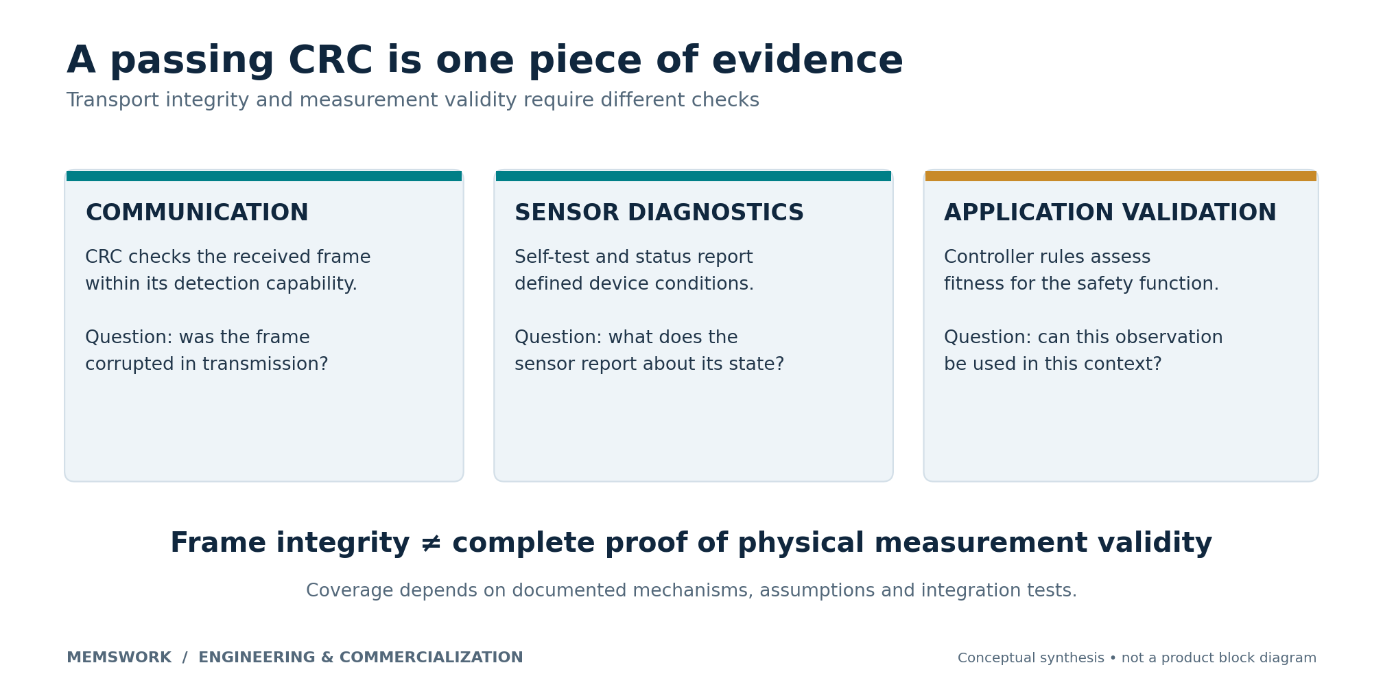
Table 1 turns that distinction into a proposed integration review. The questions are MEMSWork recommendations, not claims that the listed devices have failed a test. Each supplier should map its actual diagnostics and safety documentation to the application rather than substitute a count of diagnostic features for demonstrated coverage.
| Evidence layer | Documented basis | Proposed acceptance question |
|---|---|---|
| Sensor and signal chain | Self-test, clipping and processing diagnostics. [2] [3] | Which faults are detected, which remain latent, and under what operating assumptions? |
| Communication | SafeSPI support and device status/CRC fields. [2] [4] | How does the controller reject corrupted, missing or invalid responses? |
| Hardware safety | Hardware integration and verification within the ISO framework. [5] | Who owns each safety requirement and its verification evidence? |
| Installed behavior | ECU mounting and calibration concerns identified by Murata. [8] | Does the assembled board preserve the measurement and diagnostic assumptions? |
Table 1. A diagnostic-chain review for integrated motion sensing. Documented features and scope are sourced to [2–5,8]; acceptance questions are original MEMSWork synthesis.
Functional safety and automotive qualification answer different questions
ISO’s public scope for ISO 26262-5:2018 covers hardware safety requirements, design, architectural evaluation, random hardware failures, integration and verification. It explicitly distinguishes functional safety from nominal performance. The catalogue also identifies a draft successor under development; a draft should not be treated as an already applicable replacement. This article uses the public scope, not the paid standard’s detailed requirements. [5]
Bosch’s SMI230 illustrates why product labels need careful reading. Bosch lists automotive qualification while explicitly positioning the device for non-safety-relevant applications. Its SMI270 is separately described as developed for systems with safety targets up to Automotive Safety Integrity Level B, or ASIL B. These are different intended uses, even though both combine inertial measurements. [6] [7]
For procurement, request the applicable safety manual, failure analysis, assumptions of use and integration responsibilities. Confirm what documentation is available and under what access terms. ST’s public launch does not provide enough evidence to assign a specific ASIL capability to every new ordering code. A sensor’s stated compliance cannot substitute for the customer’s complete safety argument. [1] [5]
ECU integration moves calibration and ownership
Murata’s SCH1633-D05 announcement provides a complementary commercialization signal. The company describes direct mounting on electronic control units, or ECUs, and highlights the difficulty of post-assembly calibration. It attributes reduced customer temperature-calibration needs to factory characterization and compensation. These are supplier claims, not an independent comparison against ST’s family. [8]
The proposed diligence response is to test after representative assembly, mounting and environmental exposure. Track whether mechanical stress, board placement or rework changes the accepted measurement behavior. Connect those checks to MEMSWork’s supplier-qualification framework: the assembled function needs an owner, a controlled process and an acceptance record.
The practical partnership spans the MEMS supplier, ECU designer, safety engineer and vehicle integrator. Agree early on who diagnoses an apparent sensor fault and who controls configuration changes. This extends the complete-sensor commercialization test from emerging transduction mechanisms to production safety integration.
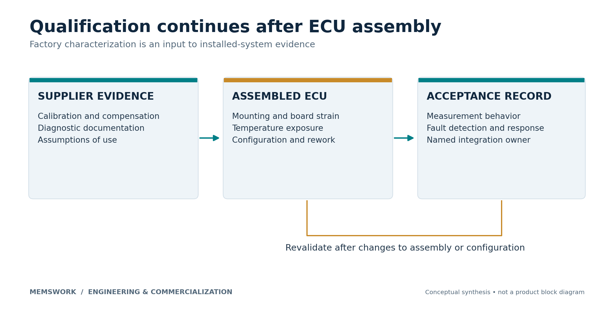
Commercial value should be measured as avoided integration effort
The business case should include component cost, board area, calibration, software validation, diagnostic testing and engineering changes. Integration can remove hardware while concentrating dependencies in a shared device or supply path. Whether that trade is attractive depends on the application’s fault-containment requirements and the evidence supporting them.
For investors and corporate strategists, the useful differentiator may be reusable safety documentation, validated drivers, production calibration and responsive failure analysis. Seek customer evidence that these assets shorten qualification or reduce recurring engineering work. Public product availability establishes a route to evaluation; it does not establish design wins, margins or pricing power.
What to Watch Over the Next 12 Months
Watch ST’s release of application documentation, supported configurations and customer qualification evidence. Track whether the EAEP range discrepancy is resolved in controlled documentation. Follow controller support that demonstrates status handling, self-test sequencing and fault response, rather than merely successful data acquisition.
Compare supplier claims about factory calibration with customer results after ECU assembly. Monitor whether integration enables reuse across safety functions or requires materially different validation each time. Customer disclosures of reduced calibration work, repeatable diagnostic tests and maintained measurement performance would provide stronger commercialization evidence than broader market-growth forecasts.
What Would Change the Thesis?
The thesis strengthens if customers demonstrate that a shared sensor and documentation package reduces qualification effort while preserving fault detection and application performance. It weakens if assembly shifts, undocumented diagnostic assumptions or difficult fault isolation require extensive custom engineering. A simpler architecture meeting the same safety requirements at lower total cost would narrow the integration advantage.
The next purchasing decision should therefore center on demonstrable system behavior: which measurements are trustworthy, how invalid states are recognized and what the controller does next. A production sensor is the starting asset. A verified diagnostic chain is the deliverable.
Sources and methodology
Specifications and maturity statements come from primary supplier documentation; they are not independent comparative tests. Numerical values were checked against the cited product pages and announcement where available. No safety-coverage percentage, cost saving, market forecast or adoption volume is inferred. The review framework and commercial implications are MEMSWork analysis.
[1] STMicroelectronics automotive combination-sensor announcement, October 26, 2026.
[2] STMicroelectronics NCS1012BAEP product specifications.
[3] STMicroelectronics NCS1012EAEP product specifications.
[4] SafeSPI official description and specification releases.
[5] ISO 26262-5:2018 public scope and development status.
[6] Bosch SMI230 product specifications and intended applications.
[7] Bosch SMI270 functional-safety positioning.
[8] Murata SCH1633-D05 announcement, May 26, 2026.
Last updated November 2, 2026 (Pacific). Update history: Initial assessment; future revisions will record documentation changes and customer integration evidence.