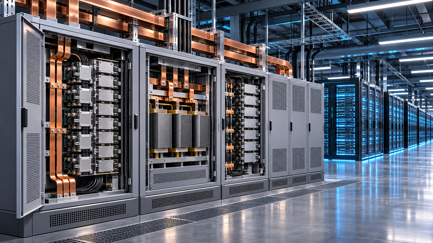
Conceptual solid-state power conversion for AI infrastructure. Original MEMSWork illustration; not a named product or electrical design. Architecture context: [4].
Solid State Transformers Enter AI Power Qualification
Recent demonstrations and capacity commitments strengthen the case for direct medium voltage conversion. Deployment decisions now depend on protection, lifetime and service evidence across the complete power system.
MEMSWork Intelligence Dashboard
| Field | Current assessment |
|---|---|
| Technology | Solid-state transformers for direct medium-voltage AC to 800 VDC conversion |
| New evidence | October 2026 brought a reported 13.8 kV laboratory demonstration and a gigawatt-scale manufacturing capacity agreement. [1,2] |
| Readiness | Vendor demonstrations and capacity reservations; deployment readiness must be assessed for each product and site. |
| Commercial question | Can fewer conversion stages produce a repeatable advantage after protection, redundancy and service costs? |
| Next evidence | Rated-power tests, fault coordination, independently scoped qualification and operating records. |
| MEMSWork assessment | Advance structured qualification and supply-chain diligence. Treat volume forecasts as contingent on customer acceptance. |
October announcements sharpen the deployment question
Solid-state transformers are becoming a concrete procurement question for AI infrastructure. Enphase reported a medium-voltage conversion demonstration in late October, while Vantage secured manufacturing capacity from Heron Power. These developments give operators reasons to evaluate equipment and reserve supply. They also expose a gap between demonstrating conversion and accepting a power system for continuous operation. [1,2]
MEMSWork’s assessment is that qualification will determine which suppliers capture durable value. An operator needs evidence that a system can protect downstream equipment, recover predictably from faults and remain serviceable throughout its operating life. A voltage demonstration answers only part of that question. The opportunity extends beyond power semiconductor vendors to isolation, sensing, magnetics, protection and test equipment suppliers.
This article examines direct medium-voltage AC to 800 VDC conversion at the facility boundary. It complements our earlier analysis of AI power infrastructure and power delivery inside AI packages. These are distinct investment and engineering decisions: a facility converter does not resolve voltage regulation close to an accelerator.
The evidence has several different meanings
On October 27, Enphase said a laboratory system converted 13.8 kV AC to 800 VDC using 132 modules, with 44 in series on each phase. It reported balanced module voltages and stable output during load steps. Its release placed megawatt-scale operation at rated power later in 2026 and customer pilots in 2027. Those milestones remained forward-looking at the time of publication. The announcement did not supply a measured full-system efficiency map or long-duration operating record. [1]
Vantage’s October 21 agreement reserved more than 1 GW of Heron Link manufacturing capacity. That is an important commercial commitment, but reserved capacity is distinct from installed, commissioned capacity. The announcement also described efficiency above 98.5 percent as a target for medium-voltage to 800 VDC conversion. An evaluation should retain that measurement boundary and target status. [2]
The supply chain is developing through several technical routes. Infineon’s September announcement identifies SiC devices for Eaton’s MVSST 2.0 platform, while Enphase describes GaN switching in its modules. Device material alone does not rank the systems. Topology, switching conditions, isolation design, thermal management and redundancy affect the resulting equipment. [1,3]
| Public signal | What it supports | What remains to establish |
|---|---|---|
| Enphase laboratory result [1] | Reported conversion and coordinated control at 13.8 kV | Rated-power system results and operating history |
| Vantage and Heron agreement [2] | Reservation of manufacturing capacity | Delivered systems and customer acceptance |
| Infineon and Eaton collaboration [3] | An identified semiconductor supply route | Performance and qualification scope for a buyer’s configuration |
| OCP architecture work [4] | Shared interfaces and multiple deployment paths | Interoperability and site-specific engineering approval |
Table 1. Interpretation of public evidence as of November 6, 2026. MEMSWork analysis based on the cited company and OCP publications. [1,2,3,4]
An 800 VDC interface permits different conversion paths
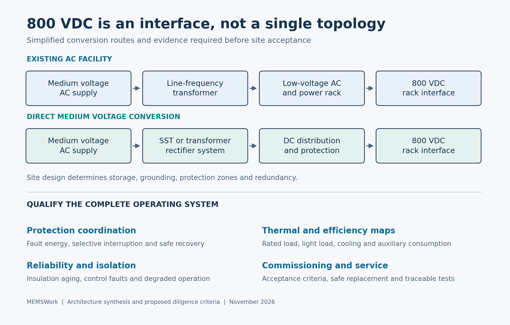
An SST combines semiconductor switching and controlled power conversion with electrical isolation, commonly using high-frequency magnetics. It still contains transformers. Moving the magnetic conversion to higher frequency changes the size, materials and insulation problem; the semiconductor stages add control and protection responsibilities. An operator buys the behavior of this combined system. [6]
The Open Compute Project describes both a side power rack using an existing low-voltage AC supply and a longer-term architecture converting medium-voltage AC directly to 800 VDC. The latter can use transformer rectifiers or solid-state transformers. Consequently, adoption of 800 VDC distribution does not establish that a particular SST topology will win every installation. Existing electrical capacity, available space and construction timing influence the choice. [4]
The electrical attraction of higher distribution voltage is straightforward. In an idealized DC branch delivering 500 kW, current is 625 A at 800 V and 1,250 A at 400 V. With unchanged conductor resistance, doubling voltage quarters resistive loss because loss follows I²R. This calculation isolates one physical relationship. It excludes converter loss, cable resizing, grounding and redundancy, and cannot establish total facility savings.
A serious bid comparison therefore needs one agreed boundary from utility connection to rack input. Include auxiliary loads, cooling, energy storage, redundant capacity and realistic operating points. Peak conversion efficiency can conceal poor utilization at light load. A reduction in conversion stages can also change where faults are isolated and which component determines availability.
Protection determines the operating architecture
SolarEdge and NVIDIA’s September protection framework addresses grounding and protection for converter-fed 800 VDC systems. SolarEdge explicitly identifies its approach as one candidate implementation and says its data center products remain under development and validation. Its release also distinguishes experience with photovoltaic protection functions from validation in a data center. That distinction matters when suppliers transfer expertise from adjacent markets. [5]
Our engineering recommendation is to qualify the converter together with downstream distribution and rack interfaces. The test plan should establish where fault energy flows, which protective device acts first, what happens to adjacent healthy loads and how stored energy is discharged before service. A fast semiconductor switch is only one element of this coordinated behavior. The selected grounding approach also changes sensing requirements and the response to insulation faults.
Useful acceptance evidence includes synchronized voltage and current traces under defined fault conditions, stated clearing thresholds and demonstrated recovery sequences. Record source impedance, storage state and firmware version alongside each test. A pass under one arrangement cannot simply be extended to a different storage configuration or distribution layout. These are proposed diligence requirements, rather than claims that every announced product has completed them.
Modularity shifts the reliability problem
Series-connected power modules distribute electrical stress, but introduce dependencies in sensing, communication and control. Qualification should establish behavior when one module’s measurement drifts, a communication link is delayed or an auxiliary supply fails. Redundancy has commercial value only when the resulting operating limits and restoration procedure are understood. Replacing a failed module also requires a safe service sequence and a controlled return to operation.
High-frequency magnetics create another diligence priority. Buyers should ask how insulation performance changes with temperature, repetitive switching stress and manufacturing variation. Production test needs to detect defects economically without substituting a brief factory screen for lifetime validation. Enphase’s earlier development update identified partial discharge, thermal behavior and distributed control among its validation areas, illustrating the breadth of the task. [6]
For MEMS and sensor suppliers, the relevant opportunity is trustworthy measurement inside the power system. Current, voltage and temperature sensing must support protection decisions under switching noise and faults. A compelling sensor specification should be accompanied by isolation behavior, drift limits, diagnostic coverage and calibration traceability. This is a supplier strategy inference from the system requirements, not an announced MEMS design win.
Commercial diligence should follow customer acceptance
Manufacturing capacity agreements can justify tooling and supplier commitments before broad deployment. They should not be counted automatically as delivered revenue or evidence of repeat orders. Investors and corporate development teams should examine acceptance conditions, commissioning responsibility, warranty scope and who bears the cost of a site redesign. Public announcements alone rarely disclose enough to resolve those questions.
Operators can structure qualification around the risks a specific site must retire. Establish the comparison architecture first, then request thermal and efficiency maps over the intended duty cycle, coordinated fault tests and a maintenance demonstration. Equipment qualification and site approval need clearly defined scopes. A certification claim should be checked against the named standard, tested configuration and permitted operating envelope.
The next commercially meaningful evidence will be rated-power operation with disclosed conditions, customer acceptance and service experience that supports subsequent orders. Until then, the sound strategy is to develop qualified alternatives while preserving the ability to use other conversion paths. Suppliers that can make protection, lifetime and commissioning evidence repeatable will be better positioned to turn today’s capacity commitments into an operating business.
Sources and methodology
This analysis uses six primary company and industry publications available by November 6, 2026. Vendor demonstrations, targets and roadmaps retain their reported status; they are not independent validation. The figure and tables are original MEMSWork synthesis. The illustrative branch-current calculation uses I = P/V and resistive loss proportional to I²R. No product efficiency ranking or market-size forecast is inferred. Recommendations and commercial implications are editorial analysis.
[1] Enphase Energy, IQ SST demonstration announcement, October 27, 2026.
[2] Vantage Data Centers and Heron Power, manufacturing capacity agreement, October 21, 2026.
[3] Infineon Technologies, Eaton MVSST collaboration, September 29, 2026.
[4] Open Compute Project, Powering the Next Era of AI and the transition to LVDC.
[5] SolarEdge, DC powertrain and protection framework with NVIDIA, September 10, 2026.
[6] Enphase Energy, IQ SST development and manufacturing update, September 8, 2026.
Last updated November 6, 2026 (Pacific). Update history: Initial publication; subsequent material revisions will record new qualification and customer evidence.